Friday, February 21, 2020

forward fuse


The forward fuselage of my slider is a little tricky.

There is a slight bend in the sub panel near the bottom; without this, the fit is terrible. I marked the bend, used an 18" brake on the outside, and a block of wood clamped to the table for the center section's bend.

.
The center web does not have prepunched holes in either the firewall, nor the web.
There are many ways others have installed this part. Here is what I did:

I first built up the web per the plans. Then I assembled it all together but put the forward skin on one hole back, so I can see to mark the location of the web on the firewall.
 I made the holes in the same vertical location as the outside ribs


 Then I put the skin on properly, drilled the top hole and clecoed.
I then removed the skin, aligned the rib to vertical, and drilled the remaining holes.

Unfortunately, the center brace is now no longer sitting on the firewall angle, so I will make a spacer. I had aligned the angle to the web based on a center line drawn on the angle. I probably should have drilled the rib to firewall first before drilling the angle to the web.


Friday, January 24, 2020

Quick Fuse update

So I have been working on the tail fairing now that the tail mechanical attach is done. I figured I would get it done before the tail comes off. The stock fairing fits really nice; much better than older posters have led me to believe. I used the cut lines, but these were too severe in the rear, so next time, I would leave a little extra there and trim, fit, trim, fit, etc. Nothing major for mounting, just takes time to find the underlying holes in the fuse. I measure the location of the holes in the fuse without the fairing; added the fairing, marked the hole locations on the fairing, then drilled a #50, then a 3/32 hole in the fairing, cleco'd and moved on to the next. Next I will enlarge the holes to #40, countersink the fiberglass for the #6 flathead screws, then enlarge the holes to #6, remove the fairing, and install the riv nuts.


After the tail fairing, I finished the inspection plates for the elevator. I did not dimple the holes for the nut plates when I built the fuse. My squeezer was too big to fit for all the holes. I had to get creative and use some blocks of wood to hold the dimple dies and a large c clamp. 


Sunday, December 8, 2019

Fuse progress

It has been awhile since I posted;  its been a fun summer, not much building thou.

Brakes are in as shown below. Still have a question if I will stay with the plastic, or move towards the AN lines. I guess the first fill tests will determine if there are any leaks. I used the solid stainless rods for the brake pivots. The brakes are very nice with good return force. I have a set of helper springs which I do not plan on installing; the pivot rods worked out so well, I don't see a need for helpers.


I am now installing the tail. The horizontal stab is on. For drilling those AN3 bolts, one really needs a 6" long drill bit.

On the vertical fin, my 90 degree drill attachment died, so I am waiting for the new one to arrive. I could drill without it, but after the experience with the horizontal stab, I would rather wait for the tool to make it easy.


Like most things, I was worried about getting the tail on right. But by taking it slow, it all worked out.


This picture shows much of the progress, tail on, engine in house, new upgraded motor mount, and sponge bob guarding it all.


I haven't decided if my next chapter will be the canopy or engine / electrical; it is pretty cold now, I might save the canopy for the warmer months.

Sunday, September 15, 2019

Fuse Details


 With all the fuselage interior parts painted, I am starting final assembly of the fuse interior. I have installed the control column and the electric aileron trim. This is all standard stuff as per plans.

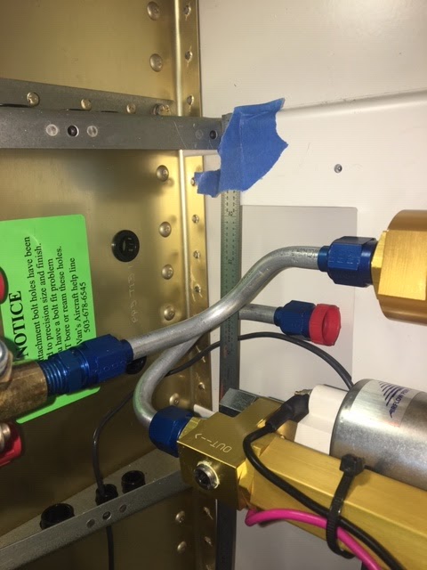
I have also installed the parking brake, ran the brake lines, fitted the fuel pump and ran the fuel lines. I will leave the fuel lines off for right now while I do the rest of the interior. I found it helpful to use house wiring to lay out the fuel and brake line routing. The brake lines to the gear legs had some 3-D bends to avoid the fuel lines.


With the seats painted and installed, I was able to make up a fake seat cushion and set the rudder pedals in the position I find most comfortable. This also allowed me to set the toe brakes with the right amount of forward lean so I wont inadvertently push on the brakes during taxi and landing. With all that figured out, I started drilling the pivot for the rudder pedals. I followed the advice of others, and am using a 3/16" solid stainless steel shaft as the pivot. It will be held in place by two cotter pins. Drilling the cotter pin holes in the stainless shaft proved to be challenging.  Here is a picture of the rod drilling and the way the pedals are installed.


Moving forward.

Thursday, August 8, 2019

fuse update 8/2019

After a very fun summer, finally got back into it. Managed to get the main gear mounts on. I am getting started on the plumbing installation. Got the parking brake valve installed using a custom bracket in the same place of the stock bracket.


Went to Oshkosh this year and saw the new nose gear that I will be retrofitting. Looks pretty beefy. But since I will be one of the first ones installing on a -9A, I am a little concerned with where everything on the firewall needs to go. Here is a pic of the nose gear on the RV7A mock up.


On my way out, found this airplane mover. Looks kind of like an RC Tank model from Tamiya. I can make one of those. Guess I need to hold onto my old RC gear a little longer.

Sunday, June 9, 2019

Interior paint

I have been working on fuselage interior. I have decided to paint the pieces separately as they are installed, instead of waiting till the interior is assembled and then trying to paint with all the nooks and crannies.

This plan has created many headaches; most of the build tasks can not be fully finished since I need to paint prior to installation.

Well I am to the point of  installing the interior systems like fuel vents, control sticks, etc.

I cant take it anymore so I decided to paint this weekend. 

Wow what a lot of painting. I bought an extra quart just so I would have it. Turns out 2 quarts will be plenty to do the interior. I am using the SW Jet Flex and this paint is totally awesome. I started painting at 10 am with the dew just about evaporated and the sun creeping out. During the session, the sun came out and it got hotter. Then towards the end it got cool and a little damp. The paint didn't miss a beat, I didn't have to change the mix ratios or gun settings in the 6 hours of painting.

Here are all the pieces laying about; tough to find enough space for drying. I still have a few covers to do, the rear bulkhead, and the upper skin of the baggage compartment. 

Now onto the gear install. I reamed the gear leg bolt holes and it was no problem. The task I dread turns out most of the time to be straight forward. A big thank you to all those who came before and wrote about it.
I am excited to complete all those tasks and continue final assembly. (And then I will clean the shop)


Monday, April 22, 2019

PH Aviation Flap Motor Install

I decided to install the new Flap Motor from PH Aviation. This flap motor replaces the stock Vans flap motor. I like the new one because it has a built in up and down stop, built in position pot to interface with the G3X, and has a different motor that may not suffer from grease contamination.

The installation is a little different than the Vans version.

First off, I made the F767 plate a little longer than the original to make sure the motor support brackets were completely contained on the plate. This eliminates a spacer and also provides more strength for the motor supports.  In the picture is the new F767 plate, and the stock F785A/F785B Backrest Brace and the stock F766A/F758 Flap actuator channel.
The new actuator is about 1 3/4" longer so I moved the actuator up higher. In the photo below, the hole to the left is the original location of the top pivot bolt. The added distance is the line on the right. I don't need to move the flap actuator the entire way to the right because I can also lengthen the actuator links to the flaps, if needed.
Here is a picture of the brackets being drilled to the Flap Actuator Channel to use AN470AD4-x rivets. The brackets are per the PH Aviation instructions that came with the flap motor. I used a AN960-416 washer and a little paper shim for spacing. The AN960-416 will become two AN960-416L washers (one on each side) and the paper shim is to ensure the flap motor is easily removed once the brackets get riveted on. The bolt will become a castle nut to allow some freedom of movement, as in the stock installation.
The assembly was drilled to the seat back brace per the plans.
Here is the final installation of the PH Aviation Flap motor. The rest of the installation follows the stock plans. (Please note, I still need to drill a hole in the Flap Actuator channel and add a doubler in order to remove the bolt)
If you notice, I have been putting off priming and painting the floors and interior panels. It is becoming a pain to keep working with things cleco'd together. I might have to bite the bullet and get the interior panels painted.