Monday, December 21, 2020

Wiring, or making rats' nests

 So I started finishing the wiring. My goal is to get all the wires in the fuselage before starting the engine and instruments. This will keep me from having to bend over and under the panel to install the wires and fuel lines on the fuselage floor. The wiring from the spar back was all done a month ago, but the wiring on the floor, in front of the spar, took some doing. This involved planning out all the wiring runs and finding enough holes in the spar to bring the wires through. It also meant I had to install the transponder and comm antennas to get those cables routed. I had to use a cat5e computer cable to get all the stick grip signals to the instrument panel; running individual wires for all the functions on the grips would have never fit through the existing spar holes. The cat5e cable used 4 pairs of 28 AWG wires in a very tight bundle, giving me 8 functions spread between the two stick grips.

I also put in the parking brake and made a bracket for the parking brake cable and the micro switch to tell me the parking brake is on.

Next up is the fuel system final install on the fuse floor. This has already been installed, but now it is time for final install.

In my spare time, I have been creating the panel wiring schematic. It seems I need 6 each RS232 outputs but only have 5 available. The G3X experts from Garmin helped me out and said if I run an independent GPS antenna for the G5, then I don't need a 6th RS232 output. I think that is what I will do; this will make the G5 a true system backup, able to get me to VFR weather if everything else goes COVID on me.

Sunday, September 27, 2020

Canopy Success

I finished up gluing the canopy to the frame and it came out well, I am very happy with the Sikaflex method and thinks it is the only way to go.

The canopy and canopy rails have been installed, along with the rear anchor blocks, and Supertracks.

I used the anchor block drill guide from RVPlasticParts.com and the angles were spot on. I had to shim one side in the tool to get the hole in the correct left and right location; this was mainly due to the fact that I had to move the anchor blocks outboard slightly to make sure there was the proper edge distance for the screw hole in the longeron.

I did a preliminary trim of the windscreen and marked the forward edge of the windscreen on the top forward fuselage skin. This will allow be to mask off and paint the portion of the skin inside the windscreen dark grey before final riveting.

I plan to finish the windscreen final trimming and canopy's fiberglass work once I am done with the instruments, electrical and engine forward installation. I want to build up my fiberglass skills on the tail feathers and cowling before tackling the canopy. (pun intended)

I am now starting on the final forward fuselage stuff working from the floor up, and firewall forward. I hope to be done Tuesday.


Thursday, August 20, 2020

Canopy Part 3 Gluing

 Got the canopy glued to the frame today. Used the Sikaflex method as outlined by VAF’s Wirejock in an earlier post.

Like everything else the fear was worse than the event. Yes it was a mess, I think I got some of the black stuff in my hair because I have a grey spot that disappeared after I was done gluing.

I used the 3m fine line painters tape. This worked out well. I tried to add a layer of electrical tape on top like Wirejock recommended, but this wouldn’t stick. After prime I pulled off the 3m tape and then Re-taped with electrical tape to make it easier to make a fillet. This didn't work. It would have been better to just pull the 3m tape after prime and leave the primer’s edge untapped.

I set the frame upright, added a bead of Sikaflex to the frame’s Spine, front and rear bows with the spacers, then dropped the canopy on top. After it was position and clamped, I added the side plywood to shape the sides and then added a bead between the side bows and canopy. I did not use the side canopy supports.

The canopy is clamped to the table so it wouldn't fall off the bench if bumped. Now I get to wait 48 hours in bliss thinking I did an excellent job. I am sure reality will set in after a few days when I unclamp and get a good look at the bonds.

 https://vansairforce.net/community/attachment.php?attachmentid=1348&d=1597618830

Sunday, August 2, 2020

Canopy Part 2 - The Big Cut

Today was a warm day, perfect for canopy work.

This weekend was all about cutting the canopy down to size. The on-line experts suggested to use the Dremel Max Saw. This worked out very well. However, they recommended the SM500 plastic blade, I found this to be a really coarse cut. I chose to use the SM510 metal blade. This blade is just like the cut off wheel Van's supplies in the kit, but for the Max Saw. With this blade, if the cuts are made carefully, there is very little clean up sanding. I took everything down to 240 grit after the cut, before moving the canopy.

The cutting wasn't as bad as others have made it out to be.It is only a (very expensive) piece of plastic. It isn't like it is a Ferrari or anything. Like everything else on this build, I was stressing over it and it turned out to be not worthy. With all the others writing of their experience, that background helped a lot. (Thank you)

I taped the canopy to the frame for a fit check using wire as a Sika spacer. Seems I have a few more trim cuts to make, so I figure another whole day in the sun and then it will be ready to bond.

I am thinking of not using the trim piece that sits on the outside, down the middle spine. It seems with the Sika bonding method, there is no need for this strip. But
I think I will need to bond on a thrust washer for the handle thou.


Sunday, July 12, 2020

Canopy Part 1b

So, today was a good day. I managed to wrestle the canopy frame into submission and I think it fits well. In total, I think a good 8 hours with a 1/2" and 3/4" conduit bender should be a reasonable time to allocate for this task.

I started with the front hoop, and then did the rear hoop today. The rear hoop requires much less force; I over bent and had to unbend several times. My only advice is to realize the levelness of the top horizontal portion is caused by the side bends. The front hoop and the side rails form a rigid structure that the rear hoop bends around. The original fit of the rear hoop was really close, I just had to do a minor tweak. I did the tweak and the shape of the rear hoop became a disaster. I freaked out for about a  minute and did the opposite of what I thought it needed and it all came back in line. I used reverse psychology and the metal tubes fell for it. Gosh I am good.

In summary, I started with the side rails (no adjustment needed), did the front hoop, and then the rear hoop. I think this order worked out well.

I used wedges under the side tubes and that was good. This allowed me to put on, and take off, the canopy frame all day as I adjusted the bends.

I am saying it is done. I will check the dimensions and fit tomorrow just to be sure it hasn't decided to spite me and regress to its prior mental state.

Here is a picture showing the wedges I used. I could not imagine doing this with the tracks in place.

I will install the tracks next and then onto the big cut.

This summer,
the hardest part of the build seems to be.... summer. Too many beaches to visit and too many hikes to take with friends, but we'll get through it.

Sunday, June 28, 2020

Finishing Kit, Canopy Part 1a

So I have been working on the fitting the canopy frame, the first step on the canopy tasks. I had taken a month off to do yard work and whatever else I could find to avoid the canopy stuff. Finally I decided it needed to get done while the weather was warm.

The canopy frame was fairly close to perfect from the factory. I had to tweak 6 spots in the front hoop. I have a little more to go in the back hoop. But the back hoop requires less force and is already  really close.

 I took the advice of others and will cut the canopy front tubes, and will put the canopy track on, after the frame is bent. I found it was much easier to do this without the tracks being on; I just used a wood space under the front tubes to raise the canopy frame up to about the right spot.

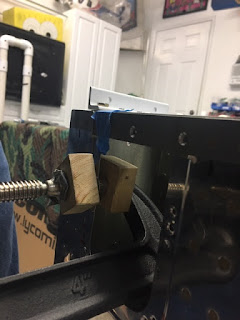
Here is how I bent the front hoop use a 3/4" conduit bender from the precision tool isle at Lowe's:


I then measured the height of the gap to make sure each side was even. I found I had to take out a slight bend on one side to make it even.


Here is the overall fit of the frame. The top height is not correct because the frame has not been sized for the track rollers.
Like everything else on this build, I stressed over this, but once I got into it, it wasn't so bad. Just keep swimming- Dora

Wednesday, May 20, 2020

Finishing Kit -Part 1 of 100

So it is time to start the finishing kit. First up is the canopy. it seems nothing has caused more trepidation from those who have gone before.

So I dive in.

The roll bar is attached first using special spacers. These have to be drilled to match the holes in the canopy rails. I drilled a pilot hole first, then flipped the spacers over and drilled the final hole from the "backside". I did this to avoid the drill bit wondering due to the "split level" front side.


The rest of the roll bar install went per plans. I did have to use a 0.025" shim under the left side to get a good fit, as mentioned in the plans.

I started fitting the canopy slider tracks too. I am installing the Supertracks from Flyboys that allow the canopy to open up farther. I order the longer RV 8 track spacer to avoid a split in the track. The trouble I ran into is bending the curve. Turns out using a simple wood block and the Armstrong method, I was able to bend it to match the full size template, no problem.


Drawing the center line on the spine spacer was a bit tricky, but I found I could use a carpenters level to draw a line holding the square against one side, then draw another line holding the square against the other side of the piece. This produces two lines on the part, with the exact center being between the two lines. In the picture below you can see the longer spine spacer,and looking closely, you can see the double line markings.

Things are slowing down now that the beach is open. But I can't let summer get in the way (too much) so I am determined to keep on making progress everyday.


Friday, April 24, 2020

Calling it- fuselage done

Well, the last lines of the fuselage kit's instructions have been completed; I am calling the fuselage kit done. It doesn't look like much progress, but a ton of work and learning.

I added a doubler for the ELT antenna. It sounds simple, but took longer than expected. Everything else went OK. I had a really good bucking bar helper; I am not sure how anyone could do this alone.
It took me a little less than two years to complete the fuse. Seems for many others, the slow build fuse takes twice as long as the wings. It seems I am no exception to this rule.

I was able to attached the side braces on the bench before installing the turtle deck; I can't image doing this on the plane. Those elevator supports I built several years ago really came in handy.

Next up, the finishing kit, starting with the canopy.


Saturday, March 28, 2020

Tail Wiring

So I am trying real hard to get the turtle deck on the tail. But first I decided I would install the wiring to the tail and the ELT mount; basically as much as I could before covering up the tail section. I really dread the thought of having to crawl in the tail to do systems installation.

So the pitch autopilot servo is in and wired, and the Canbus to the tail mounted GMU11 magnetometer is installed. I also installed a DTM connector in the tail for the electric elevator trim.
Lastly I installed the ELT mount kit from Vans. Of course there was a slight mod so that the mounting hole pattern would fit both of the most popular ELTs.

All that's left is the ELT wiring, and the doubler for the ELT antenna, then I think I can install the tail's top skin, or turtle deck.


Sunday, March 15, 2020

Subpanel Layout

So I am looking at subpanel layouts. My equipment not on the panel is all Garmin:
G3X displays (GDU 430)
GNX 375 GPS/ xpnder
GNC 255 Com1 / nav
GMA 245 Audio panel
GMC 507 Autopilot controller
G5 backup attitude

Behind the panel is:
GSU25 ADHARS
GMA245R (GTR20) Remote Radio
GEA24 Engine interface
GAD 29  ARNIC interface
GAD 27 Airframe Interface (flaps, etc)

Here is my layout.
Please provide comments on the layout, especially the pieces on the subpanel.


Thanks

Friday, February 21, 2020

forward fuse


The forward fuselage of my slider is a little tricky.

There is a slight bend in the sub panel near the bottom; without this, the fit is terrible. I marked the bend, used an 18" brake on the outside, and a block of wood clamped to the table for the center section's bend.

.
The center web does not have prepunched holes in either the firewall, nor the web.
There are many ways others have installed this part. Here is what I did:

I first built up the web per the plans. Then I assembled it all together but put the forward skin on one hole back, so I can see to mark the location of the web on the firewall.
 I made the holes in the same vertical location as the outside ribs


 Then I put the skin on properly, drilled the top hole and clecoed.
I then removed the skin, aligned the rib to vertical, and drilled the remaining holes.

Unfortunately, the center brace is now no longer sitting on the firewall angle, so I will make a spacer. I had aligned the angle to the web based on a center line drawn on the angle. I probably should have drilled the rib to firewall first before drilling the angle to the web.


Friday, January 24, 2020

Quick Fuse update

So I have been working on the tail fairing now that the tail mechanical attach is done. I figured I would get it done before the tail comes off. The stock fairing fits really nice; much better than older posters have led me to believe. I used the cut lines, but these were too severe in the rear, so next time, I would leave a little extra there and trim, fit, trim, fit, etc. Nothing major for mounting, just takes time to find the underlying holes in the fuse. I measure the location of the holes in the fuse without the fairing; added the fairing, marked the hole locations on the fairing, then drilled a #50, then a 3/32 hole in the fairing, cleco'd and moved on to the next. Next I will enlarge the holes to #40, countersink the fiberglass for the #6 flathead screws, then enlarge the holes to #6, remove the fairing, and install the riv nuts.


After the tail fairing, I finished the inspection plates for the elevator. I did not dimple the holes for the nut plates when I built the fuse. My squeezer was too big to fit for all the holes. I had to get creative and use some blocks of wood to hold the dimple dies and a large c clamp.