Sunday, November 21, 2021

Lots of progress in the last few months. Here is a summary:

The engine is in and wired. At this stage, the instructions get a little sparse so it takes some time to figure out what others have done and decide on the best course. One area of isolationism is the fuel flow sensor, that red cube in the pictures. The firewall forward kit does not make provisions for it. Fortunately, my firewall forward kit had an extra fuel hose for the tail dragger version of my plane. I was able to use this extra hose to connect the red cube. The fuel lines are a little longer than I like, but adequate. 

Secondly, the position of hole in the firewall for the mixture cable I didn't like. I ended up moving it next to the throttle cable. The new location might make it more difficult to change the oil, but that only happens once every 25 hours (once a month I hope). In addition, the factory location did not work with the length of cable that was included in the firewall forward kit. ( I am unusual because most builders install a carbureted engine; but me, naw, I had  to go fuel injected. More Power)

Lastly, I am using the manifold pressure port on the right side of the engine. This required a longer hose to the sensor. Earls in Lawndale, CA made up a new line for me while I waited. What a great resource in the LA area when I visit.

The last bit of interior painting was done on the throttle quadrant plate. I thought this would be too flimsy, but once attached to the back up cable support, this became very rigid.

The last thing I have to figure out on the engine side of the firewall is how to plumb the fuel hose from the throttle body, on the bottom of the engine, to the spider fuel distributor on the top. The Lycoming factory hose is too short. If I used the factory hose, it would make a mess of the baffles. I will have to order a new hose once the baffles are installed. 

My next step is to finish all the testing of the avionics to make sure there are no more wiring changes, and then install the last top skin on the fuselage.


Sunday, October 3, 2021

Instruments done, Engine in

 The instrument panel is installed and seems to be working well. I still have a few things to calibrate, but the radios work and I can talk to the tower. The plane can find the GPS, and receives the local glide slope fine.  I did have to re configure my radios thou. I had to make my remote radio Comm 1, and my panel mounted radio Com 2 and Nav 2 (VOR, ILS). This would allow the co pilot to work the panel radio and the pilot to work the remote radio if the pilot and co pilot wanted to split duties. The audio panel allows split comm so that pilot can talk on Com 1 and co pilot can talk on com2 to different control facilities. 

I also changed the RPM sense to use the P-lead as per the latest revision of the Garmin software. This avoids one more wire thru the firewall and avoids having to put a RPM sensor on the mag case.


After the instruments were in, we installed the engine. The plane is still on the wood stand to make things easier to get to. I read all the previous suggestions and it went in with little trouble.
I put the bottom bolts in first and then the top.
I also had to change the support brace prior to releasing all the load onto the fuselage; the old position of the brace was cause a slight warpage of the bottom skin so i moved it forward to just next to the firewall. Much better now.
I think it only took us 1 hour, at the most.

The Snap-on open end box fit three nuts perfectly; like it was designed for this. I had to grind a craftsman sacrificial box end to fit the upper left nut. That one has very little clearance from the push rod to the bolt to slide the wrench on.

Now it is time to finish up the instrumentation wiring with all the engine sensors; install the baffles, controls and cowling, and continue marching on towards first flight in 2022.
 

Friday, September 3, 2021

Final Assembly Chapter 23


 Final assembly is continuing. Have installed instrument panel permanently in plane. First picture was just after  riveting with few wires connected. 


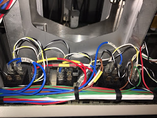
Since that time I have wired everything up from plane to black boxes except engine temp sensors; those I will wait on until engine is installed.

I have all the antennas connected to the radio trays, so technically I wont emit smoke if I turn the radios on; I am prepping to light up the instruments before the engine goes in. 


Tuesday, June 8, 2021

Final Fuse Push

 Now that the panel is done enough to install, I have been working to finish all the fuselage stuff to limit the amount of work I need to do on my back once the panel is installed. 

First off was to finish the fuel lines. I have been putting this off because I didn't want to keep hitting them as I walked around the airplane. Now it was time to install. My hat is off to those who did this per the plans; I was not able to get a single line from the valve to the wing roots, so I broke it up into three pieces. Ya the extra breaks have more potential for leaks, but I am using 200 PSI fittings for a maximum of 8 psi; so I think it will be OK.

 
Next  up was figuring out the GPS and XM antenna placements. I was planning on putting them just forward of the firewall, exactly like what is NOT recommended due to heat. Then I thought about a place on the glare shield, but I didn't like seeing over them all the time. I thought the rear turtle deck would not work because I was afraid the canopy would not slide over them. Turns out someone posted a picture on line and guess what, the canopy clears them by a large margin. So I ended up installing the GPS antennas in the preferred location on top the fuselage. Now I have to spend $200 on 50 feet of RG400 cable to run to the back. Oh well. Here are my antennas installed temporarily so that I can run the antenna wires. I think this is going to work out great!
I also installed the parking brake handle. I had to redo the idiot light switch. (I was an idiot the first time). I had it activate when the lever pushed on it, but a slight shaking would cause it to be intermittent. I changed it so that it is activated when the lever sweeps past it; no longer susceptible to vibrations. 
I still need to torque everything, and then torque strip. 
Next up is prep for the engine mount install, than install the panel, than hang the engine. Lots to do.


Wednesday, May 19, 2021

Panel Bench Wiring Done!


Well today I am calling done the bench wiring of the Panel and Sub-panel. I cant think of anything else I can do on the bench before installing it and hooking everything up to the stuff already wired in the plane.

Here are the pics on the bench of all the stuff. There is really a lot of boxes and wiring in this panel. It didn't look so bad when viewing the schematic several months ago. 

I can't light it up without the antennas hooked up, so I will just pretend that it is wired correctly. 

I have been neglecting the fuselage wiring; so now it is time to clean that up, and get all the foot well stuff done prior to putting in this panel structure.


Saturday, April 10, 2021

Instrumentation Continuing

 After 3 months of wiring, the instruments are nearly done. I figure there are a dozen computers to wire up with about 250 terminations. Nothing too hard, but it takes time. In final wire check of sub-panel, I found 3 miss wires out of about 250 terminations; not bad. (None of them were smoke producers, just data lines.)

I decided to add a CO detector at the last minute after watching a you tube video. This was easy since I had left service loops.

With the sub-panel wiring done, I am working on the cutting the instrument panel for all the switches and stuff.


Sunday, February 14, 2021

Center Stack Wiring

 Just a quick update.
Center radio stack wiring nearly done. About 100 terminations so far. Only another 150 or so to go.

If you look closely at the picture, lots of things going on. For example, supports modified to allow screens to be high on panel. Connectors are mounted on brackets in approximate locations to allow nice harness routing. Harness pass thru holes in sub panel. Fuse block installed. Wires are labeled with printed heat shrink tubing. Splices and terminations are inside back shells for greater reliability and better EMI (don't try this at home, it can go wrong if not carefully done)


Sunday, January 17, 2021

Firewall and Engine Prep

 Great progress these past few months. It seems as one gets closer to being done, many more decision need to be made by oneself. The plans become "a guide" and not instructions carved in stone.

For the engine, it seems there are two oil configuration choices for fixed pitch prop. The difference for a fixed pitch is the oil that normal goes to the prop needs to go somewhere and not build up pressure in the forward part of the crank. There seems to be two ways to do this when using fixed pitch. First is to use the normal oil return to the governor  by letting the oil return through the governor cover that has a milled slot. This is shown in the picture of my cover plate. The second way is to open up the front crank plug, punch a hole in the rear crank plug, and then reinstall the front crank plug. Then one could remove the governor line from the front to the back and plug the fitting holes in the case. Since I had the governor line in place and the front crankshaft plug already factory installed, I just verified the rear governor cover had the milled slot and than put everything back together as shipped from factory. This way a future conversion to a constant speed prop will be easy. I also installed the alternator on the vac pump pad and checked the torque on the fittings that were factory installed. I still need to put the oil and fuel fittings onto the accessory case.

For the firewall, most of the electrical stuff that attaches to the firewall is installed. I still have to assembly the wires with lugs and stuff. Here is how I did the current shunt and the ANL fuses. I have everything with 12V power on fusible links or ANL fuses before passing thru the firewall. I am using a single shunt set up to read battery charge and discharge current. This will tell me if the alternator is putting out sufficient current to have extra to charge the battery or if my load is too great and discharging the battery. Please note the copper bus bars are not straight. This was done to allow some expansion and contraction so as not to pull or push on the contactor  terminals.  Moving forward (Pun Intended)