Thursday, August 8, 2019

fuse update 8/2019

After a very fun summer, finally got back into it. Managed to get the main gear mounts on. I am getting started on the plumbing installation. Got the parking brake valve installed using a custom bracket in the same place of the stock bracket.


Went to Oshkosh this year and saw the new nose gear that I will be retrofitting. Looks pretty beefy. But since I will be one of the first ones installing on a -9A, I am a little concerned with where everything on the firewall needs to go. Here is a pic of the nose gear on the RV7A mock up.


On my way out, found this airplane mover. Looks kind of like an RC Tank model from Tamiya. I can make one of those. Guess I need to hold onto my old RC gear a little longer.

Sunday, June 9, 2019

Interior paint

I have been working on fuselage interior. I have decided to paint the pieces separately as they are installed, instead of waiting till the interior is assembled and then trying to paint with all the nooks and crannies.

This plan has created many headaches; most of the build tasks can not be fully finished since I need to paint prior to installation.

Well I am to the point of  installing the interior systems like fuel vents, control sticks, etc.

I cant take it anymore so I decided to paint this weekend. 

Wow what a lot of painting. I bought an extra quart just so I would have it. Turns out 2 quarts will be plenty to do the interior. I am using the SW Jet Flex and this paint is totally awesome. I started painting at 10 am with the dew just about evaporated and the sun creeping out. During the session, the sun came out and it got hotter. Then towards the end it got cool and a little damp. The paint didn't miss a beat, I didn't have to change the mix ratios or gun settings in the 6 hours of painting.

Here are all the pieces laying about; tough to find enough space for drying. I still have a few covers to do, the rear bulkhead, and the upper skin of the baggage compartment. 

Now onto the gear install. I reamed the gear leg bolt holes and it was no problem. The task I dread turns out most of the time to be straight forward. A big thank you to all those who came before and wrote about it.
I am excited to complete all those tasks and continue final assembly. (And then I will clean the shop)


Monday, April 22, 2019

PH Aviation Flap Motor Install

I decided to install the new Flap Motor from PH Aviation. This flap motor replaces the stock Vans flap motor. I like the new one because it has a built in up and down stop, built in position pot to interface with the G3X, and has a different motor that may not suffer from grease contamination.

The installation is a little different than the Vans version.

First off, I made the F767 plate a little longer than the original to make sure the motor support brackets were completely contained on the plate. This eliminates a spacer and also provides more strength for the motor supports.  In the picture is the new F767 plate, and the stock F785A/F785B Backrest Brace and the stock F766A/F758 Flap actuator channel.
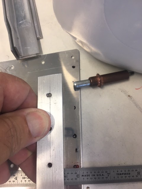
The new actuator is about 1 3/4" longer so I moved the actuator up higher. In the photo below, the hole to the left is the original location of the top pivot bolt. The added distance is the line on the right. I don't need to move the flap actuator the entire way to the right because I can also lengthen the actuator links to the flaps, if needed.
Here is a picture of the brackets being drilled to the Flap Actuator Channel to use AN470AD4-x rivets. The brackets are per the PH Aviation instructions that came with the flap motor. I used a AN960-416 washer and a little paper shim for spacing. The AN960-416 will become two AN960-416L washers (one on each side) and the paper shim is to ensure the flap motor is easily removed once the brackets get riveted on. The bolt will become a castle nut to allow some freedom of movement, as in the stock installation.
The assembly was drilled to the seat back brace per the plans.
Here is the final installation of the PH Aviation Flap motor. The rest of the installation follows the stock plans. (Please note, I still need to drill a hole in the Flap Actuator channel and add a doubler in order to remove the bolt)
If you notice, I have been putting off priming and painting the floors and interior panels. It is becoming a pain to keep working with things cleco'd together. I might have to bite the bullet and get the interior panels painted.

Sunday, January 6, 2019

Fuse, Part 5, Rolling, Rolling, gotta keep them rolling


Big day today, I rolled the fuselage canoe. It is just a symbolic step about half way through the fuselage construction.


There was quite a bit of work to get to this point. Painting the inside was the most stressful for me having not touched a paint gun since last century; but in the end, this was not nearly as bad as I had imagined.

Along the way, I did run into a few things that had me puzzled. First off was the holes for the tail fairing. The plans led me to believe all the holes in the rear longeron get dimpled and countersunk. However, others have warned that several of these holes get tapped for screws to hold the fairing. The fairing is part of the finishing kit, so I don't have that piece. Vans was kind enough to send me some pictures of what holes need to be tapped. So I left these un-dimpled. From what I understand, the quick-build kits have these dimpled, so no crime either way. Here are the pictures from Vans showing the holes that can to be left un-dimpled.

Secondly, I had trouble with the jog in the forward longeron fitting properly. Vans approved me using a second angle and some shims as shown below. This is a little different than my previous post.
Lastly, several of the screws in the forward bulkhead need to be countersunk so that the rivets would be flush for the gear mounts. This is how I did that. I also had to use shorter rivets to make it all workout.
A few of the rivet lengths need to be adjusted. Just had to pay attention to catch them.
Overall, this part of the build gave me the most nightmares, but like eating an elephant, it was conquered one bite at a time.
Now back to building.


Friday, October 12, 2018

Fuselage, Part 5 Edge Distance

As others have said, the forward fuselage becomes an exercise in edge distance. This means the closeness of a hole to the edge of the aluminum. It is suppose to be 2 times the hole diameter from the center of the hole to the the edge. So a little fancy math gives 1 1/2 hole diameters from the edge of the hole to the edge of the metal.

This first became a problem for the F-623A clips that couple the mid and aft fuselages. In the picture you will see the plans-built version all primed and ready to go. The non-primed are the ones I remade to solve the edge distance problem as evident by the "x" on the part, where the hole would have ended up.

 Everything was going great until I arrived at the F-719 installation. These parts are "joggled" to overlap the F-904 bulkhead. My parts didn't fit very well; and the rivet would have been right at the jog.  I ended up adapting, as builders often do, and used a second angle piece as shown in the picture. I will round the edges so that these pieces play nice with the passengers. 

Following others advice, I was very careful to measure all edge distances before drilling. Some are VERY close. I followed the plans and drilled the holes in the F-713 longeron on the center line, this puts the hole in the F-9101 close to the edge. But there is also a 3/16" bolt that goes thru this longeron for the front tank mount; everything must be dead nuts on. The F-9101 needs to have the edges radius per the plans, otherwise the holes in F-713 are pushed pretty far off as shown in the picture.


So far the kit pieces do fit together very well. I think most of my trouble has been operator error. No more beer for you- Seinfeld


Sunday, September 2, 2018

Fuselage, Part 4

Much progress has been made on the fuselage. I realize this is a long build; much like the wings, I look at the instructions and see what I have accomplished and what I have left to go, and just gain a little more respect for all those who have gone before. I keep telling myself there are over a thousand flying, and at least one that has flown around the world. Thanks to all those trailblazers.

The fuse continues with the center section assembly. Much of it to plans, but the crotch belt hold downs were an update that is not explicitly called out in the instructions. I decided to do this while installing the ribs. This allowed me to use solid rivets. I also had to use the 90 degree drill adapter and a 12" #30 bit. I was able to use solid rivets due to my doing this as the center section was assembled. (The separate instructions assume a retrofit and used pulled rivets.) 


Riveting the center section had its difficult moments. It took some effort to get to the rivets for the center ribs and the center-rear bulkhead. If I was to do this again, I would start with the most central ribs and rivet from the center to the outside squeezing the rear and crotch belt supports, and using the rivet gun for the very front.

Once the ribs were in, I turned it up on the edge of the bench and most of the skin rivets were easy with my awesome helper holding the bar. I had to remove the control column brackets and 2 of the 4 seat belt anchors to get access.


To me it was not clear when to dress the R-915 side ribs. I did those after the structure and skin were riveted on and this worked out well. These must be fluted to match the curve of the side skins. I was able to use the prepunched holes and the seat floor edge to judge the fluting. They came out well.


After all this fun, here is the milestone shot. The one that shows real progress is being made. (At least until it comes time to take it apart to deburr and dimple.)
I realize I did not install the optional AHDRS mount in the aft fuselage. I am thinking I am going to put it up front to avoid more wires and tubing going through the center section. That is my story and I am sticking to it. ;-)


Saturday, July 14, 2018

Fuse, part 3

So I am working on the aft fuselage. Like many others, I had trouble with the F779 bottom fuse skin at the rear. This is really thick and pre bent. Well sort of.  I had trouble getting the prepunched holes to lie up between the F779 and the bulkheads F710, F711, and F712. I was determined to have these pieces fit without inviting my neighbor, Mr Armstrong, to come over. Finally got it all lined up.

The trick was tweaking F779. First I made a jig to get the sides bent more by hitting it with a rubber mallet on the end; I tried using a piece of pipe on the bends, but this didn't do much. Then I used the rolling trick from the rudder build to finish bending the curve to 90 degrees. The metal has a lot of spring back, so I couldn't due this by hand. Everything fits well now.